X, Y and Z positions and angle positions.
The UR robot is a 6 axis robot so the calculation of the robot coordinates is a complex equation that involves rotation vectors as well. It might seems simple to say “I just want the robot to go to a X, Y Z position – yes but then there are many different Pose the robot can have at that exact X, Y, Z position – for example should the head be from the left – or right – or in an angle or upside down from below – they can all reach the exact same X, Y Z position. Therefore the angle or rotation of the tool head can be different and therefore thrown into the equation.
For the better understanding then focus on the X, Y and Z position first.
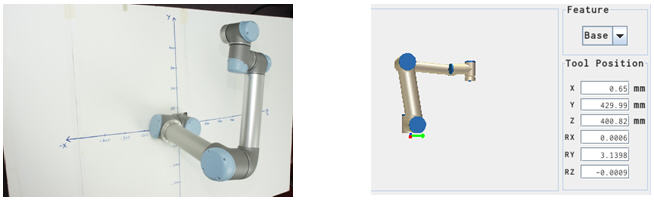
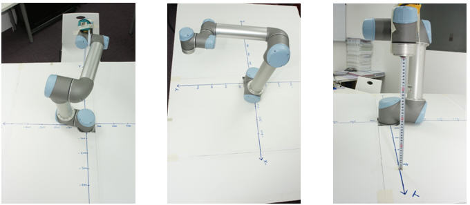
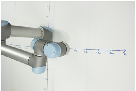
Just consider the robot in an X, Y, and Z coordinate system.
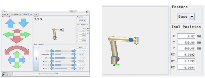
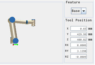
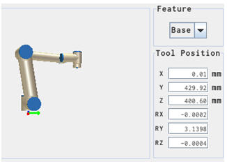
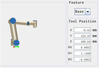
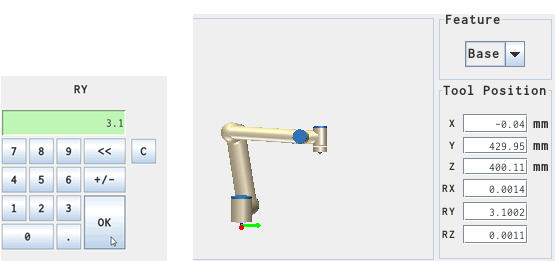
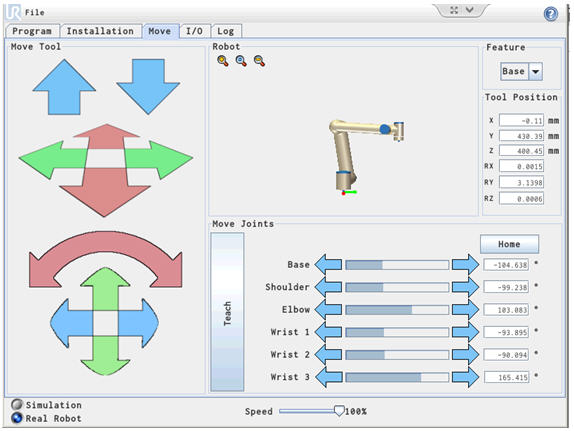
This shows the robot at X = 0 mm, Y = 430 mm and Z = 400 mm. Easy to see in the coordinate system. And this can also be seen on the Information window in the Move screen.
In this case the X, Y, Z coordinates is shown with the base as reference.
Don’t worry too much about the Rx, Ry and Rz yet – they will be explained later. But it is important to understand and to sink in that – the X, Y and Z coordinates are seen from the Base position in this case (can actually be changed, but that will complicated the explanation) – whereas the Rotation of the Tool head is seen from the tool head position itself. This is paramount to understand otherwise it is very easy to get confused.
Maybe consider your arm – the finger tip position is the X, Y and Z coordinates from your body – whereas the Rotation of your wrist is the Rx, Ry and Rz – with the X, Y and Z axis shifted to your fingertip.
X, Y, Z vector versus Joint angles.
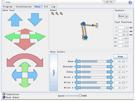
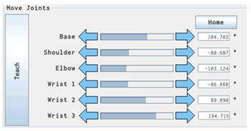
This part of the screen shows the Joint angle of each joint. This does not directly tell where the robot head is position in the space. Note each is expressed in degrees.
Each joint can turn + 360 degrees and -360 degrees i.e. a total of 720 degrees.
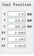
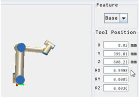
The part of the screen shows the tool Position as a 6 axis vector with the X, Y, Z position in mm seen from the base as reference.
Whereas the tool head rotation is seen as angles expressed in Radians as seen from the tool head point as reference.
As seen above the Joint angles are shown in degrees, but this could also be expressed in Radians. And this is important to notice because later when used in script programming – these joint angles has to be provided in Radians.
Formula for converting Radians to degrees on UR and degrees to Radians.
(Radian / 3.14) x 180 = The Degree shown in the Move Screen.
3.14 x (The Degree shown in the Move Screen) / 180 = Radian
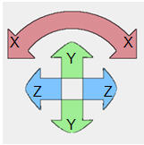
RX, RY and RZ rotation vector movement.
The position of RX, RY and RZ is a Rotation Vector based on the physics of the robot i.e. the length of the arms and joints and the rotation of the joints.
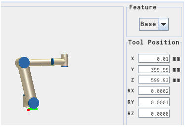
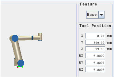
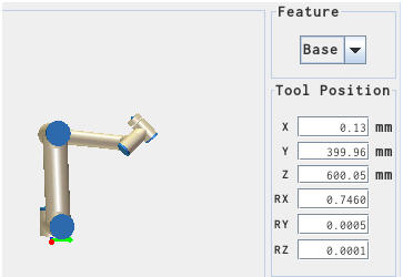
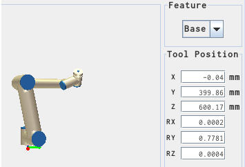
The calculation of the tool head position is equations where these factors are a part. The normal tool head position facing down is 180 degree from the origin of these vectors. So to illustrate the changes to RX, RY and RZ then rotate the tool head to face straight up so all RX, RY and RZ can be 0.
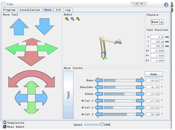
Put the robot in this pose i.e. X = 0, Y = 400 mm, Z = 600 mm, RX = 0, RY = 0, RZ =0
Robot Pose.
The RX, RY and RZ can be changed Individually by these controls.
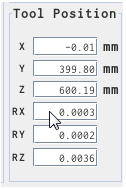
The RX, RY and RZ can also be changed by key in the value of the desired angle.
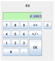
Current value for RX.
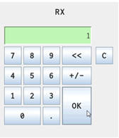
Type in the desired angle in radians and click OK.
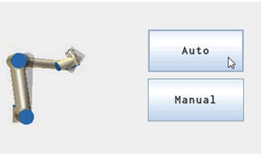
Press Auto the perform the move.
The robot tool head has turned around the X axis.
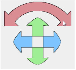
Using the Arrow keys for the tool head.
Set the robot in position X = 0, Y = 400 mm, Z = 600 mm, RX = 0, RY = 0, RZ =0
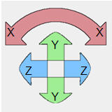
Press one of the X rotation arrows.
The robot has turned around the X axis
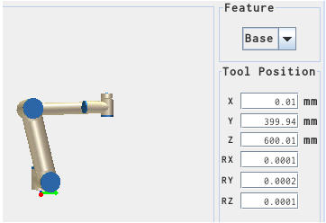
Set the robot in position X = 0, Y = 400 mm, Z = 600 mm, RX = 0, RY = 0, RZ =0
Press one of the Y rotation arrows.
The robot has turned around the Y axis
Set the robot in position X = 0, Y = 400 mm, Z = 600 mm, RX = 0, RY = 0, RZ =0
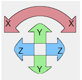
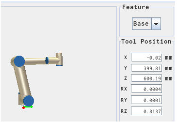
Press one of the Z rotation arrows.
The robot has turned around the Z axis (Not easy to see on this graphics, but only the last joint with the connector has turned.
(Better to see on a physical robot).
When the robot tool head is facing down the RX is turned 180 degree i.e. 3.14 radians.
When the robot head is turned around the Y axis then RX and RZ is changing value because the entire equation involve the 180 Degree offset of the tool head.
Move to X, Y, Z, Rx, Ry, Rz position.
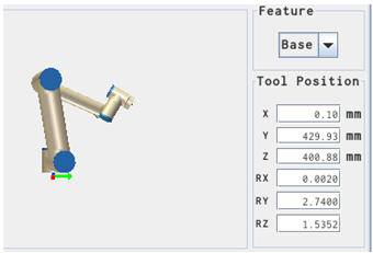
In these examples the Feature is shown from a “Base” perspective i.e. set the Feature to “Base” view.
The X, Y and Z are the position of the robot tool head in mm as in a coordinate system.
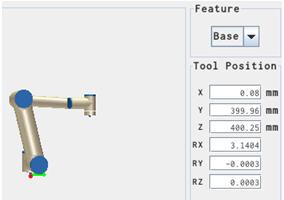
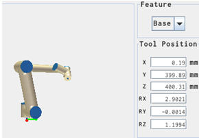
Rx, Ry and Rz are the orientation of the Tool head as an angle in Radians around the axis mentioned after the “R” i.e. Rx is the angle around the X axis in Radians.
X = 0 mm, Y = 430 mm, Z = 400 mm
X = 0 mm Y = 430 mm Z = 400 mm
Turn the robot tool around an Axis.
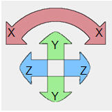
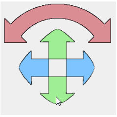
Observe how there is a Red, Green and Blue line below the robot graphics. The Red line illustrates the X axis, the Green line illustrates the Y axis and the blue line illustrates the Z axis. These entire Axes are seen from the tool head point.
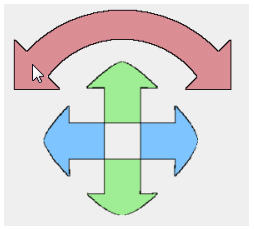
On the left side of the screen under “Move Tool” is the same colour used on the arrows to indicate which axis is moved.
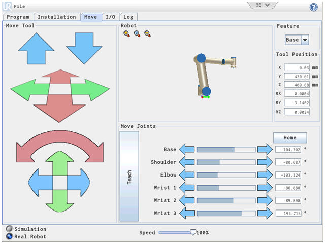
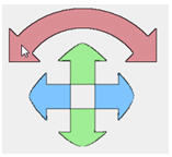
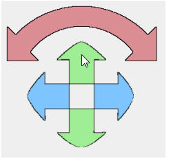
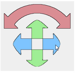
Pay attention to these arrows.
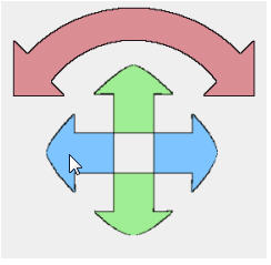
Focus now only on these arrows and press the Red arrow on the left side.
Turn the Tool head around the X axis (Rx).
Turn the Tool head back around the X axis (Rx).
Notice how the robot turn the tool head along the X axis.
Turn the Tool head back around the X axis (Rx)
Notice how the robot turn the tool head along the X axis.
Turn the Tool head around the Y axis (Ry).
Turn the Tool head back around the Y axis (Ry).
Notice how the robot turn the tool head along the Y axis.
Turn the Tool head back around the Y axis (Ry).
Notice how the robot turn the tool head along the Y axis.
Turn the Tool head around the Z axis (Rz).
Turn the Tool head back around the Z axis (Rz).
Notice how the robot turn the tool head along the Z axis.
(Not easy to see on the graphics because only the last joint turns).
Turn the Tool head back around the Z axis (Rz).
Notice how the robot turn the tool head along the Z axis.
(Not easy to see on the graphics because only the last joint turns).
The X, Y, Z, Rx, Ry, Rz will change when the tool head is manipulated according to the physics of the robots arms and body structure.
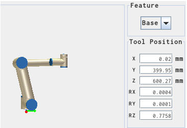
Turn the robot tool around the Y axis (Ry).
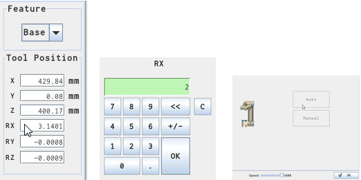
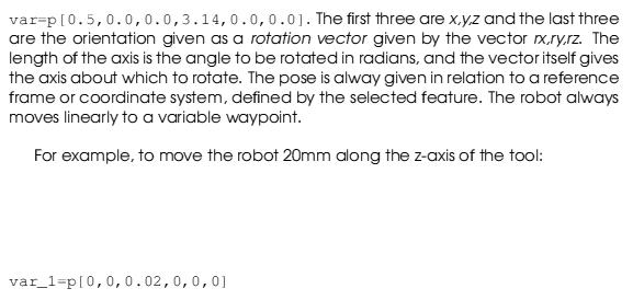
Instead of using the arrows as manipulators, it is also possible to key in the angle of the tool head position. This is easiest to understand when the robot is aligned along the X and the Y axis. In first example the robot is aligned along the Y axis i.e. X = 0.
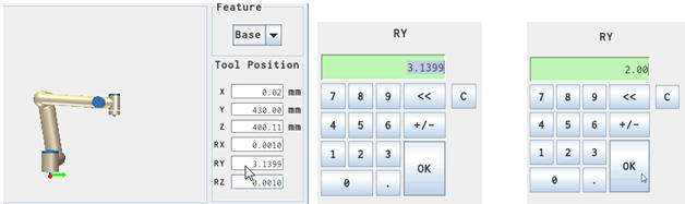
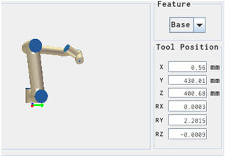
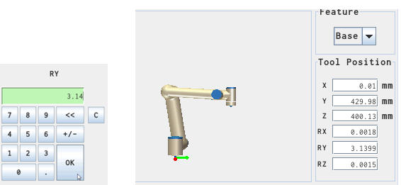
Press the Ry bar. Change from 3.14 to 2.00 Radians.
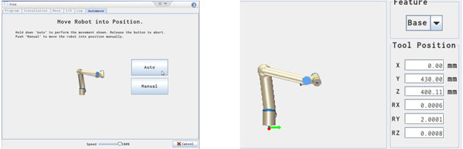
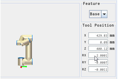
Press “Auto” button to perform the move. Ry now changed to 2.00 Radians.
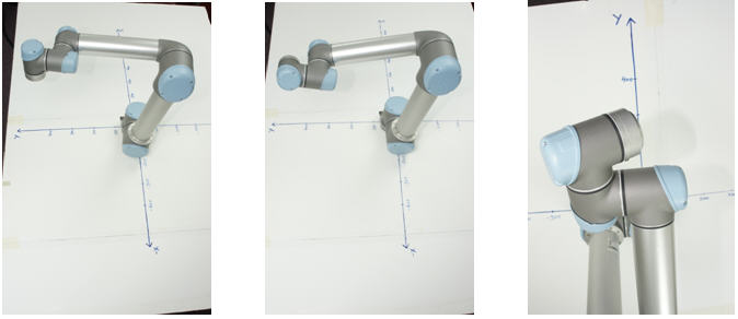
Robot at Ry = 3.14 Rad. Robot at Ry = 2.00 Rad. Robot at Ry = 2.00 Rad
Change the robot back to Ry = 3.14 Radians.
Press the Ry button and set Ry to 3.14.
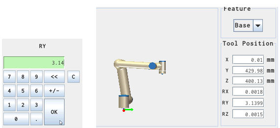
Try just a small change e.g. set the Ry to 3.1. Notice how the robot did the move immediately without the need for pressing “Auto” because of the small change.
Robot now at Ry = 3.1 Radian (Toolhead slightly tilted).
Set the robot back to Ry = 3.14.
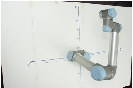
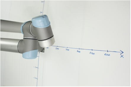
Next example will show the robot aligned along the X axis i.e. Y = 0. Change the Robot to the Y = 0 position.
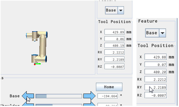
Use the “Base” arrow bar to move the robot over to the Y = 0 position.
The robot swing over the position the toll head at the X axis i.e. Y = 0.
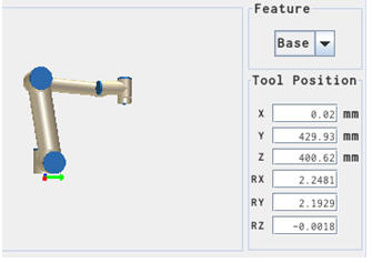
Notice how the Rx and Ry also change along the way because the tool head also move.
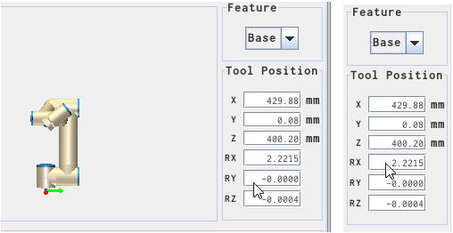
Change the Ry = 0.
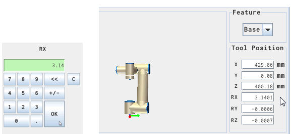
Change the Rx = 3.14
Robot at Y = 0 and the tool head align with the X axis.
Press the Rx bar. Change the Rx = 2.00. Press “Auto” to perform move.
The tool head has now turned around the X axis.
Rotated around the X axis.
Move the Robot by X, Y, Z positions via Script.
Move the tool head around the Y axis.
In this example the Robot is at X = 0, Y = 430 and Z = 400 with the tool head at Ry = 3.14 Radians.
Then this script command is send to the Robot.
s.send (“movej([-1.8263219632699421, -1.7319098497843228, 1.7991931614989278, -1.6389153321983159, -1.5723347175650684, 2.8868157860256334], a=1.3962634015954636, v=1.0471975511965976)” + “\n”)
time.sleep(10)
s.send (“movej(p[0.0000000000000000, 0.4300000000000000, 0.4000000000000000, 0.0000000000000000, 2.0000000000000000, 0.0000000000000000], a=1.3962634015954636, v=1.0471975511965976)” + “\n”)
Note:
The “p” (here highlighted) in front of the parameter change from Joint position move to a Pose move.
In this example the tool head is moved from Radian 3.14 to Radian 2.0 around the Y axis.
Notice how the X, Y and Z remain the same, but how the RY is changed from 3.14 to 2.00 by the script command below.
Using this description in the Script manual as Inspiration.
Notice hot he Tool head has turned around the Y axis.
Move the tool head along the Y axis.
It is also possible to move in a direction of an axis. In this example the robot is moved 200 mm in Y axis direction.
s.send (“movej([-1.8263219632699421, -1.7319098497843228, 1.7991931614989278, -1.6389153321983159, -1.5723347175650684, 2.8868157860256334], a=1.3962634015954636, v=1.0471975511965976)” + “\n”)
time.sleep(10)
s.send (“movej(p[0.0000000000000000, 0.4300000000000000, 0.4000000000000000, 0.0000000000000000, 2.0000000000000000, 0.0000000000000000], a=1.3962634015954636, v=1.0471975511965976)” + “\n”)
time.sleep(10)
s.send (“movej(p[0.0000000000000000, 0.6300000000000000, 0.4000000000000000, 0.0000000000000000, 2.0000000000000000, 0.0000000000000000], a=1.3962634015954636, v=1.0471975511965976)” + “\n”)
See the result below
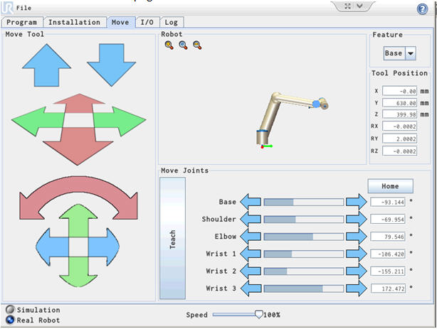
Complete program for moving the robot 200 mm in Y axis. (Note the change from 0.43000 to 0.63000.
# Echo client program
import socket
import time
HOST = “192.168.0.9” # The remote host
PORT = 30002 # The same port as used by the server
s = socket.socket(socket.AF_INET, socket.SOCK_STREAM)
s.connect((HOST, PORT))
s.send (“set_analog_inputrange(0, 0)” + “\n”)
data = s.recv(1024)
s.close()
s = socket.socket(socket.AF_INET, socket.SOCK_STREAM)
s.connect((HOST, PORT))
s.send (“set_analog_inputrange(1, 0)” + “\n”)
data = s.recv(1024)
s.close()
s = socket.socket(socket.AF_INET, socket.SOCK_STREAM)
s.connect((HOST, PORT))
s.send (“set_analog_outputdomain(0, 0)” + “\n”)
data = s.recv(1024)
s.close()
s = socket.socket(socket.AF_INET, socket.SOCK_STREAM)
s.connect((HOST, PORT))
s.send (“set_analog_outputdomain(1, 0)” + “\n”)
data = s.recv(1024)
s.close()
s = socket.socket(socket.AF_INET, socket.SOCK_STREAM)
s.connect((HOST, PORT))
s.send (“set_tool_voltage(24)” + “\n”)
data = s.recv(1024)
s.close()
s = socket.socket(socket.AF_INET, socket.SOCK_STREAM)
s.connect((HOST, PORT))
s.send (“set_runstate_outputs([])” + “\n”)
data = s.recv(1024)
s.close()
s = socket.socket(socket.AF_INET, socket.SOCK_STREAM)
s.connect((HOST, PORT))
s.send (“set_payload(0.0)” + “\n”)
data = s.recv(1024)
s.close()
s = socket.socket(socket.AF_INET, socket.SOCK_STREAM)
s.connect((HOST, PORT))
s.send (“set_gravity([0.0, 0.0, 9.82])” + “\n”)
data = s.recv(1024)
s.close()
s = socket.socket(socket.AF_INET, socket.SOCK_STREAM)
s.connect((HOST, PORT))
s.send (“movej([-1.8263219632699421, -1.7319098497843228, 1.7991931614989278, -1.6389153321983159, -1.5723347175650684, 2.8868157860256334], a=1.3962634015954636, v=1.0471975511965976)” + “\n”)
time.sleep(10)
s.send (“movej(p[0.0000000000000000, 0.4300000000000000, 0.4000000000000000, 0.0000000000000000, 2.0000000000000000, 0.0000000000000000], a=1.3962634015954636, v=1.0471975511965976)” + “\n”)
time.sleep(10)
s.send (“movej(p[0.0000000000000000, 0.6300000000000000, 0.4000000000000000, 0.0000000000000000, 2.0000000000000000, 0.0000000000000000], a=1.3962634015954636, v=1.0471975511965976)” + “\n”)
data = s.recv(1024)
s.close()
print (“Received”, repr(data))
Disclaimer: While the Zacobria Pte. Ltd. believes that information and guidance provided is correct, parties must rely upon their skill and judgement when making use of them. Zacobria Pte. Ltd. assumes no liability for loss or damage caused by error or omission, whether such an error or omission is the result of negligence or any other cause. Where reference is made to legislation it is not to be considered as legal advice. Any and all such liability is disclaimed.
If you need specific advice (for example, medical, legal, financial or risk management), please seek a professional who is licensed or knowledgeable in that area.
Author:
By Zacobria Lars Skovsgaard
Accredited 2015-2018 Universal Robots support Centre and Forum.