Planes and position variables 1
This article is similar to Planes and Position variables 2 and does the same move arround a box, but with a different method.
This article describes a way to setup different planes and how to use them for move from one plane to another.
This article uses variables and lists (also sometimes reffered to as “arrays”) to create waypoints and how variable waypoints can be manipulated with an offset defined in the variables.
The Universal-Robots is a 6 axis robot which means it has 6 turning joints. Therefore a position can be described with a set of data in a list – either as joint angles – or as a pose with cartisian cordinates. Such list can be –
[j1, j2, j3, j4, j5, j6] when representing the robot position with joint angles.
p[X, Y, Z, Rx, Ry, Rz] when representing the robot position with cartisian cordinates also called a “Pose”.
Notice the “p” in front of the second list indicationg that it is a Pose representation.
This examples will use the Pose representation.
The Universal-Robots is by default set to use the Base as plane reference, but it is also possible to setup user defined planes.
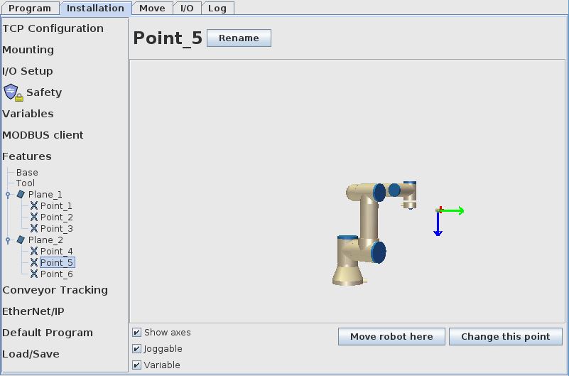
This is done in the Installation – Features menu. Notice the two planes Plane_1 and Plane_2 setup here is exactly the same as in the previous example “Working with planes and variables 2” – so if they already has been set they can be used again and therefore programming can start already by going to the program example below.
In this example 2 different planes will be created with a program example for how to move between them.
A plane is setup by setting 3 points where the first point is the plane normal (the origin of the user plane). The second point is the Y axis direction of the new plane and therefore the second point is set in the desired Y direction from the plane normal. The third point is the X axis direction of the new plane and therefore the third point is set in the desired X direction from the plane normal.
The X and Y direction for this plane is using the tool head as reference – and in the Installation – TCP configuration the orientation of the X and Y from the tool head can be seen.
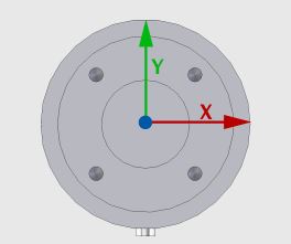
Notice the Y direction is opposite direction of the tool head I/O connector – and notice the X direction as seen on the above illustration.
The tool I/O connector is used to observe the orientation of the tool head when setting the feature points of the plane.
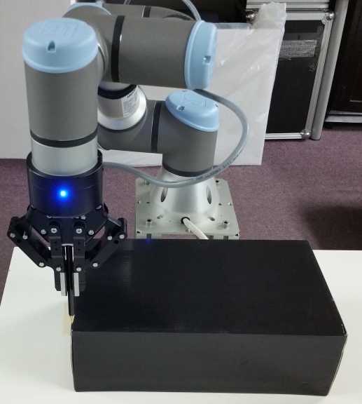
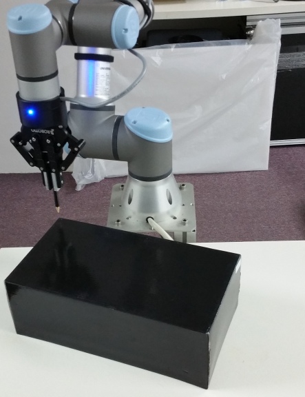
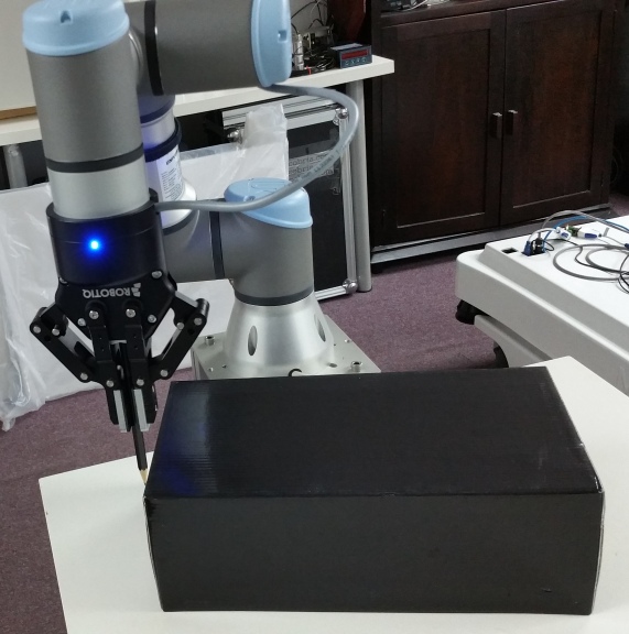
Notice on below photos that the I/O connector is pointing towards the robot – because the Y axis is opposite as the I/O connector – and is this case it is desired that the Y axis is pointing away from the robot.
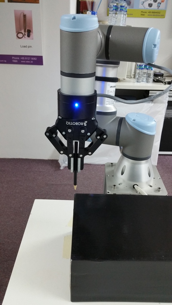
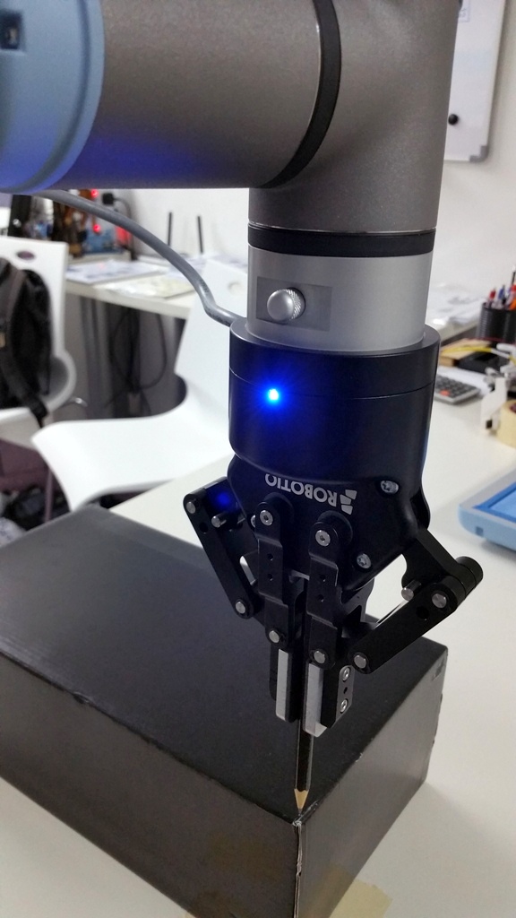
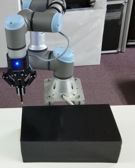
Move the robot to the desired position of the origin of the first user plane (Plane 1). Here in this example a black box is used as object to move around. The lower left corner near the robot is used as the origin for the user plane. Pay attention to the orientation of the tool head rotation – in this case the blue light on the Robotiq gripper is exactly opposite the I/O connector and therefore the blue light in this case indicate the Y axis – and the Y axis for this feature plane 1 – point 1 is carefully aligned with the direction of the side edge of the black box (the object).
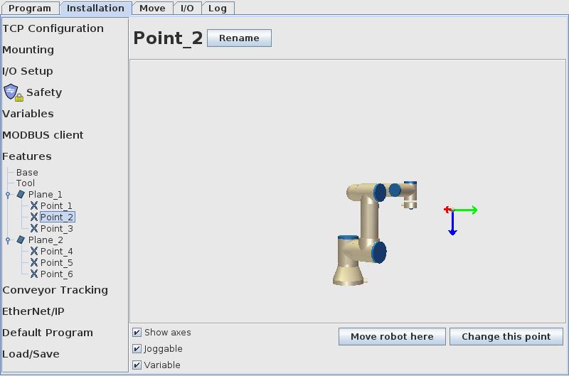
When the robot has been moved into position set this as the Plane 1 – Point 1. Make sure the “Show axes” – “Joggable” and “Variable” is ticked because this will enable the see the axis color in the Move screen and enable the possible to jog with the plane as reference in the Move screen and it will enable the the possibility to use the plane as a variable in the program.

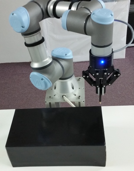
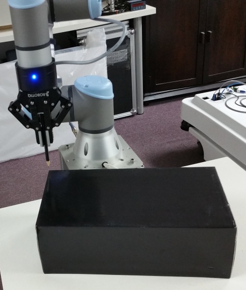
Move the robot in the desired Y direction of this user plane – in this case that is upwards exactly along the side edge of the black box. It is not important how long the robot is moved along the Y axis, but as long as possible gives the best result because then the angle to the X axis becomes more accurate.
In this case the robot is moved to the corner of the black box.
When the robot has been moved into position set this as the Plane 1 – Point 2. Make sure the “Show axes” – “Joggable” and “Variable” is ticked because this will enable the see the axis color in the Move screen and enable the possible to jog with the plane as reference in the Move screen and it will enable the the possibility to use the plane as a variable in the program.
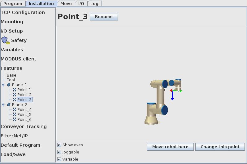
Move the robot in the desired X direction of this user plane – in this case that is sidewards exactly along the side edge of the black box. It is not important how long the robot is moved along the X axis, but as long as possible gives the best result because then the angle to the Y axis becomes more accurate.
In this case the robot is moved to the corner of the black box.
When the robot has been moved into position set this as the Plane 1 – Point 3. Make sure the “Show axes” – “Joggable” and “Variable” is ticked because this will enable the see the axis color in the Move screen and enable the possible to jog with the plane as reference in the Move screen and it will enable the the possibility to use the plane as a variable in the program.
As this article will show how it is possible to move between planes – it is necessary to create one more user plane so a difference in the robot movement can be observed.
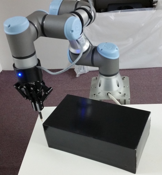
So the black box is moved in an angle in order to illustrate another plane orientation.
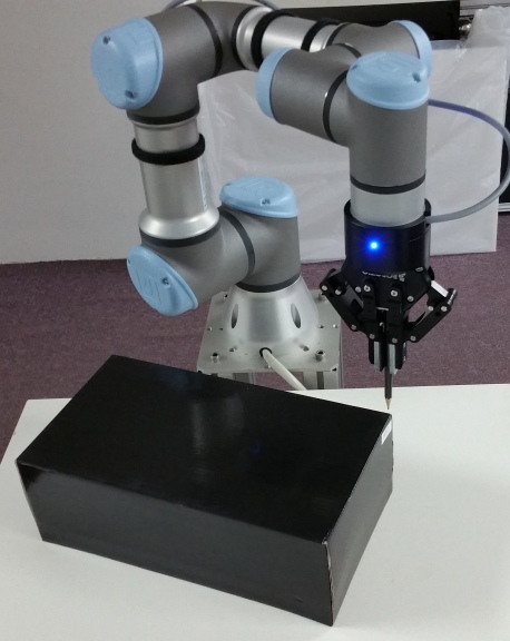
Move the robot to the desired position of the origin of the second user plane (Plane 2). The new lower left corner near the robot is used as the origin for the user plane. Pay attention to the orientation of the tool head rotation – in this case the blue light on the Robotiq gripper is exactly opposite the I/O connector and therefore the blue light in this case indicate the Y axis – and the Y axis for this feature plane 2 – point 4 is carefully aligned with the direction of the side edge of the black box (the object).
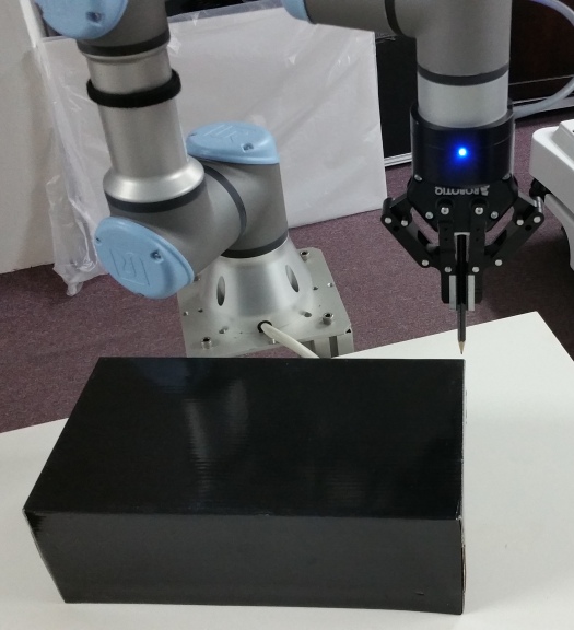
Because the box is now in an angle the tool head is also rotated a little to match up the angle of the black box -see a second photo of this below. The blue light which is the Y axis is aligned with the side edge of the black box.
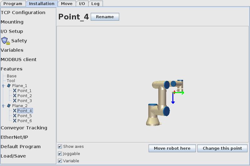
When the robot has been moved into position set this as the Plane 2 – Point 4. Make sure the “Show axes” – “Joggable” and “Variable” is ticked because this will enable the see the axis color in the Move screen and enable the possible to jog with the plane as reference in the Move screen and it will enable the the possibility to use the plane as a variable in the program.
Move the robot in the desired Y direction of this user plane 2 – in this case that is upwards exactly along the side edge of the black box. It is not important how long the robot is moved along the Y axis, but as long as possible gives the best result because then the angle to the X axis becomes more accurate.
In this case the robot is moved to the corner of the black box.
Again notice e the box is now in an angle the tool head is also rotated a little to match up the angle of the black box – see a second photo of this below. The blue light which is the Y axis is aligned with the side edge of the black box.
When the robot has been moved into position set this as the Plane 2 – Point 5. Make sure the “Show axes” – “Joggable” and “Variable” is ticked because this will enable the see the axis color in the Move screen and enable the possible to jog with the plane as reference in the Move screen and it will enable the the possibility to use the plane as a variable in the program.
Move the robot in the desired X direction of this user plane 2 – in this case that is sidewards exactly along the side edge of the black box. It is not important how long the robot is moved along the X axis, but as long as possible gives the best result because then the angle to the Y axis becomes more accurate.
In this case the robot is moved to the corner of the black box.
Again notice e the box is now in an angle the tool head is also rotated a little to match up the angle of the black box – see a second photo of this below. The blue light which is the Y axis is aligned with the side edge of the black box.
When the robot has been moved into position set this as the Plane 2 – Point 6. Make sure the “Show axes” – “Joggable” and “Variable” is ticked because this will enable the see the axis color in the Move screen and enable the possible to jog with the plane as reference in the Move screen and it will enable the the possibility to use the plane as a variable in the program.

Also make sure that for both Plane 1 and Plane 2 the “Show axes” – “Joggable” and “Variable” is ticked because this will enable the see the axis color in the Move screen and enable the possible to jog with the plane as reference in the Move screen and it will enable the the possibility to use the plane as a variable in the program.

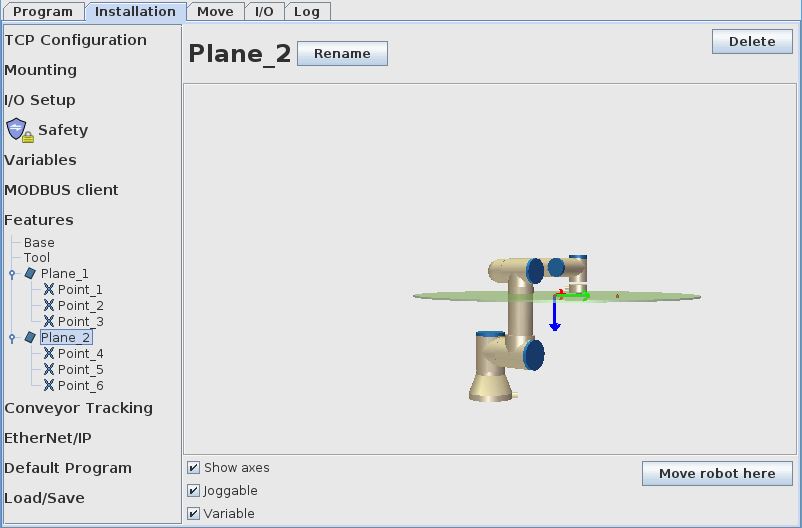
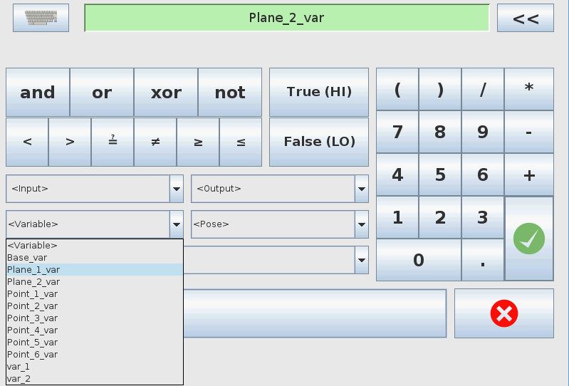
When the “Variable” is ticked then it is possible to select the Plane variable in drop down menus when programming the robot.
Notice that there is now two variables with the names Plane_1_var and Plane_2_var which can be used in the program as reference.
Now the planes are ready to be used in the program.
Variable Table:
Var_1 = A copy of the Plane_1_var.
Var_2 = A copy of the Plane_2_var.
Program description:
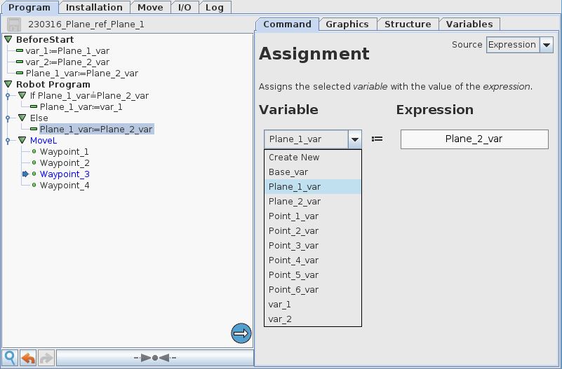
Below is an example of a Universal-Robots polyscope program that move between two different planes and thereby follow to edges of the black box in two different orientations.
First a copy of the Plane_1_var and Plane_2_var is made in order to get them back when needed.
There is only 4 waypoints and they have been programmed as the 4 corner position of the black box when the black box is in its Plane 1 orientation. The 4 waypoints has been created as “fixed” waypoints, but because there is a change in plane reference – then the 4 “fixed” waypoints also change accordingly to the plane reference.
After one program run the feature is moved to the second plane by changing the Plane_1_var to the contents of Plane_2_var.
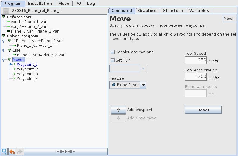
Also notice that the MoveL is set to use the Plane_1_var as reference. So in the program the contents of Plane_1_var is changing between the original Plane_1_var and at next program run to the contents of Plane_2_var and thereby the robot change motion and follow the plane that is active in Plane_1_var.
Below is a video that show the program run. Notice the change in plane orientation.
(If video does not play – try this link)
Disclaimer: While the Zacobria Pte. Ltd. believes that information and guidance provided is correct, parties must rely upon their skill and judgement when making use of them. Zacobria Pte. Ltd. assumes no liability for loss or damage caused by error or omission, whether such an error or omission is the result of negligence or any other cause. Where reference is made to legislation it is not to be considered as legal advice. Any and all such liability is disclaimed.
If you need specific advice (for example, medical, legal, financial or risk management), please seek a professional who is licensed or knowledgeable in that area.
Author:
By Zacobria Lars Skovsgaard
Accredited in 2015 Universal Robots support Centre and Forum.