
Injection Moulding Machine Tending with Euromap 67 interface:
Help to setup Universal-Robots with Injection Mouldning Machine using Euromap 67 interface.
Application Description:
This example show a Universal-Robot tendig a Injection Moulding Machine (IMM) for insert mould i.e. the robot will pick a part from a table and place that part into the IMM mould and when the moulding is done – then the robot will pick the same part out of the IMM again and place back on the table – so this can also be compared to a Pick & Place application and in this case the Euromap 67 interface between the Universal-Robot and the IMM is used.
Function description:
Since this type of IMM has a door that open and close between each mould cycle then also additional proximity sensors has been applied in order to detect when the IMM door is open or closed.
There is also used proximity sensors to detect when a part is ready on the table to be inserted into the mould. And there is a sensor on the pneumatic chuck that pick the part out of the mould which detects if the “runner” is present and not stuck inside the mould .
Therefore there is additional signal exchange aside from the E67 signals which are connected to the Universal-Robot input/output which can be seen on the diagrams below.
The emergency stop and safety circuits are interlinked in a Euromap 67 interface and on some IMM the safety circuit will open when the door open on the IMM and then it might be necessary to work on that on the IMM.
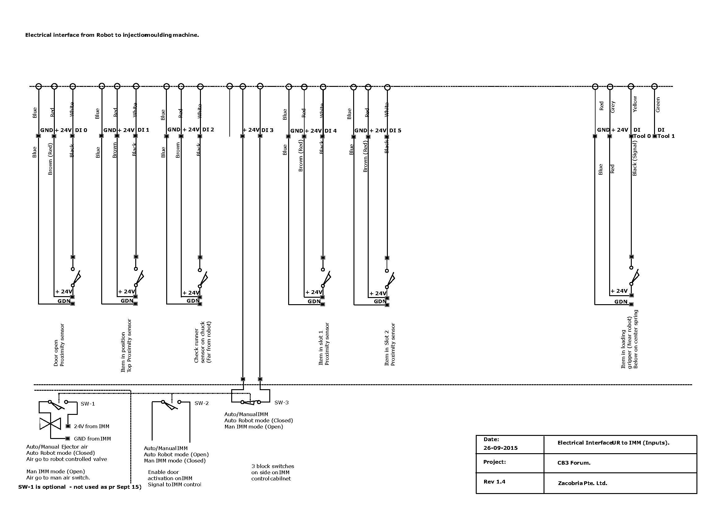
I/O table Inputs:
DI0 = IMM Door Open.
DI1 = Item in position in gripper.
DI2 = Check runner sensor on chuck.
DI3 = Auto/Manual IMM switch.
DI4 = Item in slot 1.
DI5 = Item in slot 2.
DI Tool 0 = Item in loading gripper.
E67 Inputs on Universal-Robots.
E67 in: Moulding Area Free
E67 in: Mould Closed
E67 in: Mould Open Position
E67 in: Enable Opperation With Robot
E67 in: Ejector Back Position
E67 in: Ejector Forward Position
E67 in: Core Pullers 1 in Pos 1
E67 in: Core Pullers 1 in Pos 2
E67 in: Core Pullers 2 in Pos 1
E67 in: Core Pullers 2 in Pos 2
E67 in: Intermediate Mould Opening
E67 in: Reject
E67 in: Manufacutre Dependant, Z
E67 in: Reserved ZC5
E67 in: Reserved ZC6
E67 in: Reserved ZC7
E67 in: Robot Emergency Stopped
E67 in: Supply From Robot
E67 in: Moulding Machine 24V Present
E67 in: Emergency Stop Machine
E67 in: Safety Devies of Machine
I/O table Outputs:
DO0 = Gripper 1 shut
DO1 = Gripper 1 open
DO2 = Gripper 2 shut
DO3 = Gripper 2 open
DO4 = Activate ejector
DO5 =
DO6 = Auto/Manual IMM
DO7 = Activate cycle
DO Tool 0 = Vacuum on
DO Tool 1 = Purge vacuum
E67 Outputs on Universal-Robots.
Mould Area Free (15)
Enable Mould Closure (1)
Enable full Mould opening (2)
Robot operation mode (8)
Enable ejector back (9)
Enable ejector forward (10)
Move core pullers 1 to pos 1 (11)
Move core pullers 1 to pos 2 (12)
Move core pullers 2 to pos 1 (13)
Move core pullers 2 to pos 2 (14)
Manufacture dependant A5 (0)
Manufacture dependant C5 (4)
Manufacture dependant C8 (7)
Reserved for future use A8 (3)
Reserved for future use C6 (5)
Reserved for future use C7 (6)
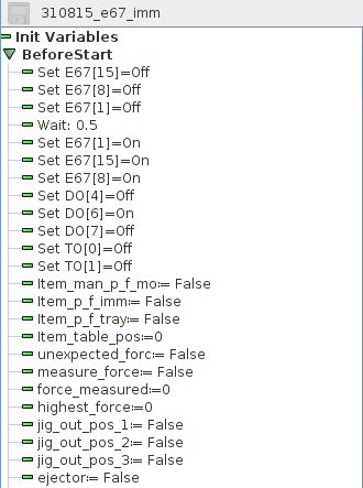
Variable Table:
Item_man_p_f_mo = Item manually removed from mould
Item_p_f_imm = Item picked from mould
Item_p_f_tray = Item picked from tray
Item_table_pos = Item position on table
unexpected_forc = Unexpected high force measured
force_measured = Actual force meansured
highest_force = highest force measured
jig_out_pos_1 = First check of jig in position
jig_out_pos_2 = Second check of jig in position
jig_out_pos_3 = Third check of jig in position
ejector = maunal press ejector
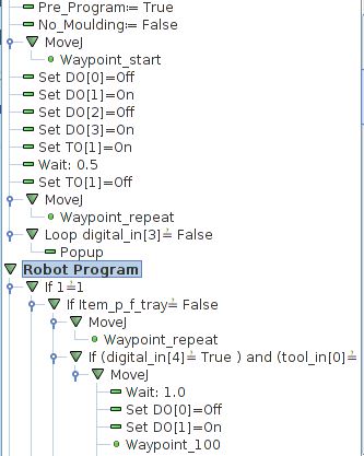
Pre_Program = First program cycle check
No_mould = No mould at last cycle
Figure 1: IMM inteface electrical diagram robot inputs.
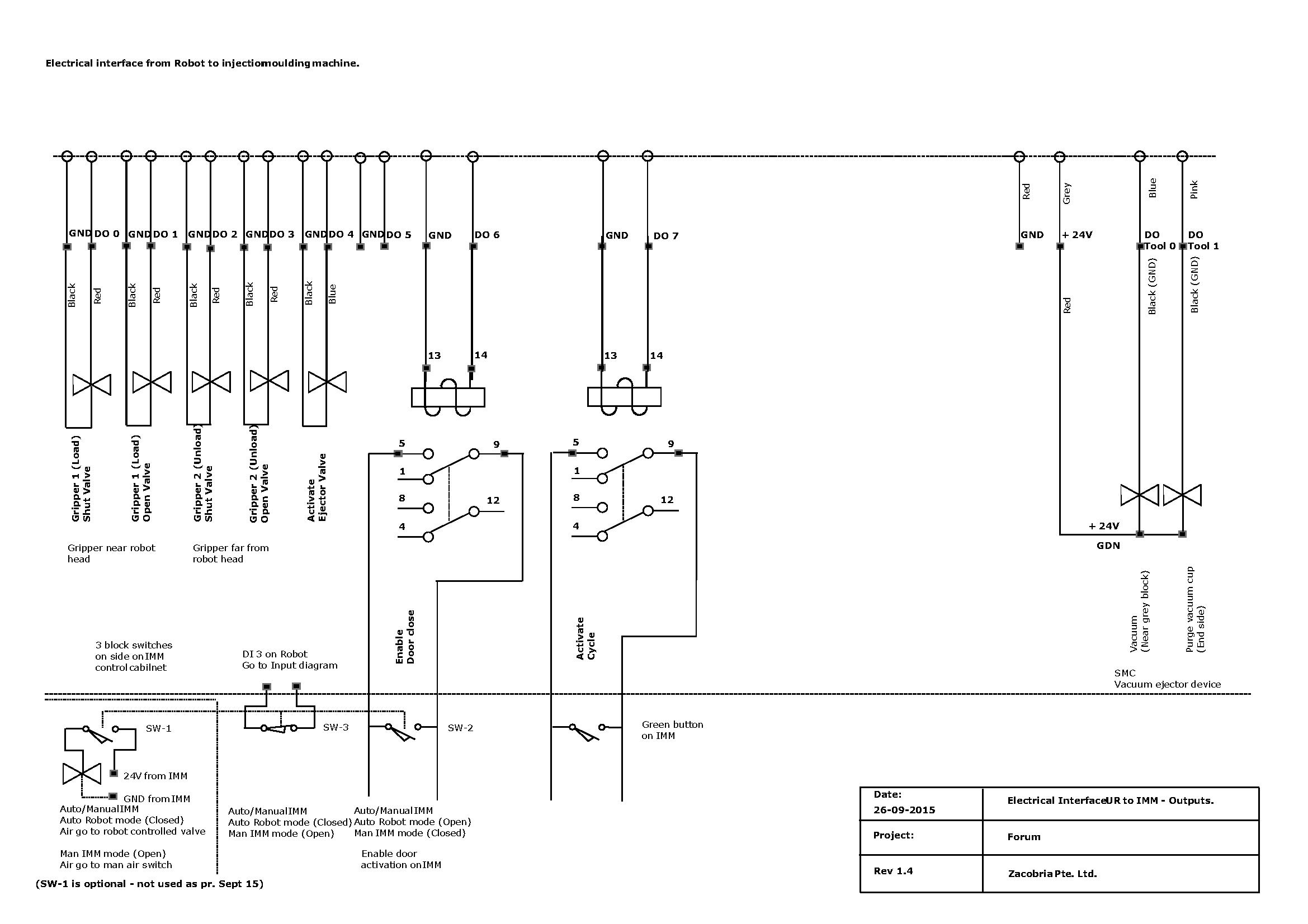
Figure 2: IMM inteface electrical diagram robot outputs.
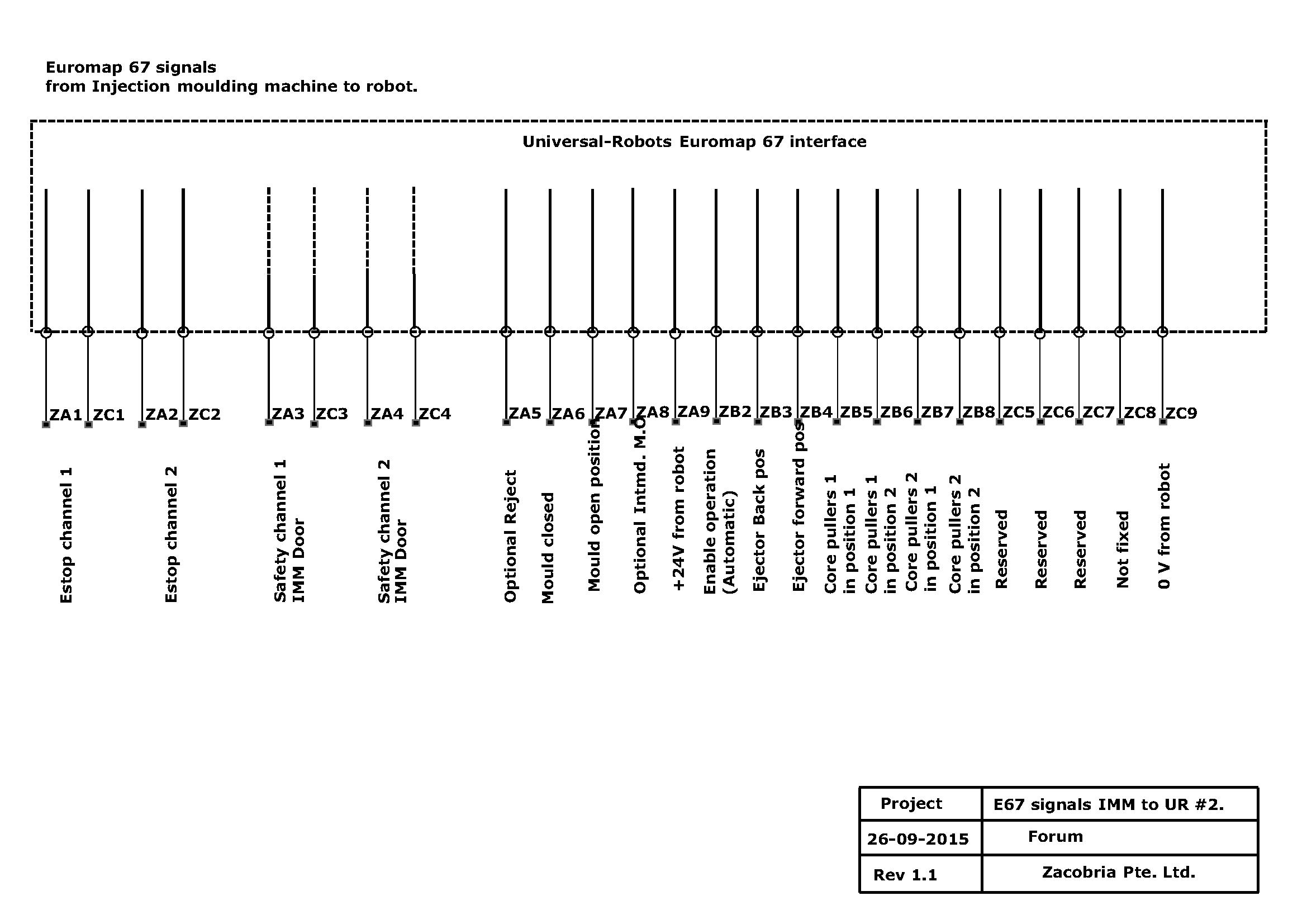
Figure 3: E67 IMM to UR electrical diagram.
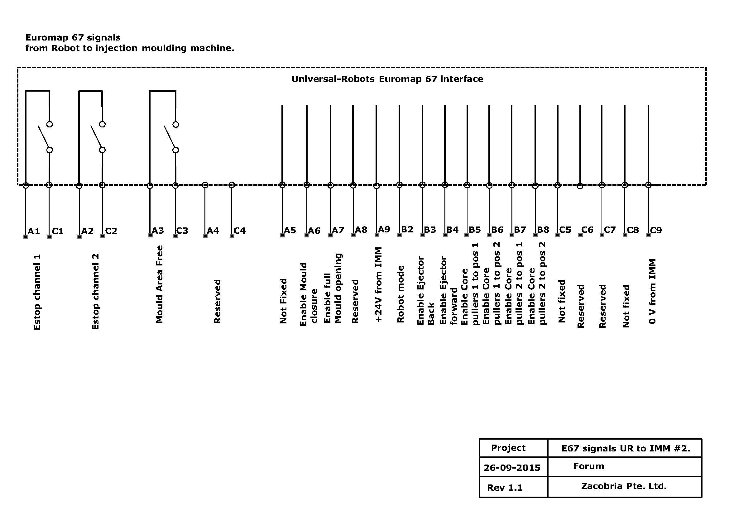
Figure 4: E67 UR to IMM electrical diagram.
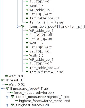
Program description:
In the BeforeStart routine outputs and variables are set to a desired value in order to send signal to IMM that the robot is active.
The first move of the robot is the release any items that might be still located in the gripper from previous run and there for the robot move to a place where it can open the gripper and let the item come out of the gripper.
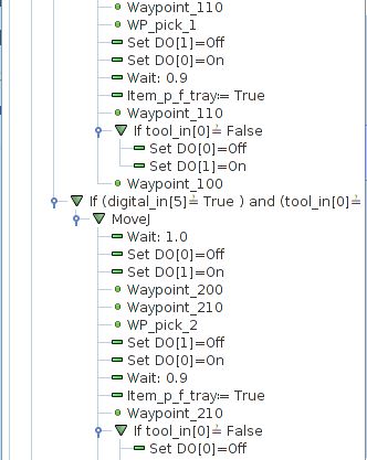
Then the robot await signal from one of the two proximity sensors that is located under each pick position in order to signal when an item is ready to be picked. When the signal is high the robot will pick an item and go to a waiting position just outside the IMM machine.
When the IMM has open the mould and open the door a signal mould area free through the Euromap 67 is set and also an external signal from a proximity sensor detecting the door is open – then robot move into the mould area and pick the processed item and insert a new item to be ready for insert mould.
During this process the robot check several things. When picking the processed item from the IMM the gripper closes arround the “runner” – if the runner is not in place it can mean the runner is stuck inside the IMM machine and can cause error for next cycle if not removed. Therefore the robot will display an error messages if this occur – and the runner has to be manually removed by operator. When the robot os placing an item in the mould – then the robot measure the force in a thread when going down and if the force is unexpected high it can mean there was to much obstruction and the item might be misplaced. Also the two proximity sensors on the gripper are checked at a position where the item must be fully down in the mould. If one of these check misses then the robot will not give a “start cycle” to the IMM because the item is not placed correct inside the mould. Instead the robot will go out and place the processed item on the table and pick a new item to be loaded and try again. The robot will in most cases be able to pick the wrongly placed item and there for there is no error messages displayed for this event.
If the item is placed correct then the robot will go out from the mould area and when it is safely outside then it will send a start signal to the IMM which cause the IMM to close the door and start the mould cycle – at the same time the robot will move to the place position on the table and release the processed item.
And then a new robot cycle starts.
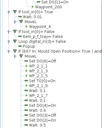
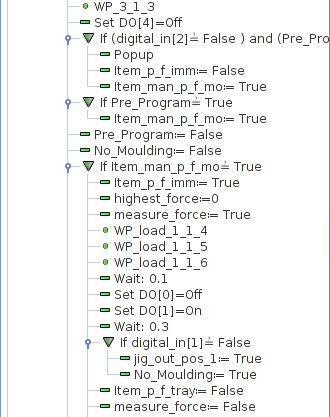
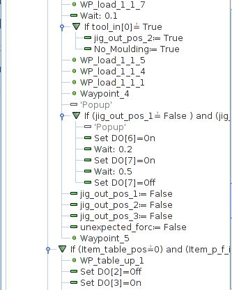
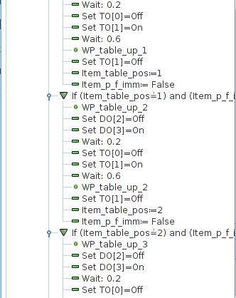
The program as Pseudo code in text format can be downloaded below:
For the application is used:
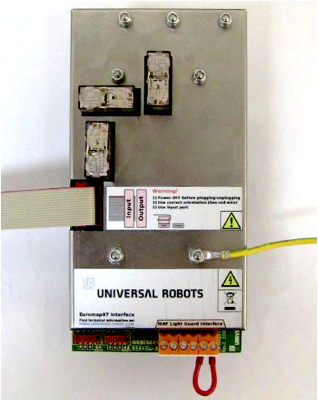
Euromap 67 Interface from Universal-Robots.
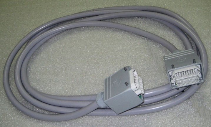
Euromap 67 Interface cable from Universal-Robots.
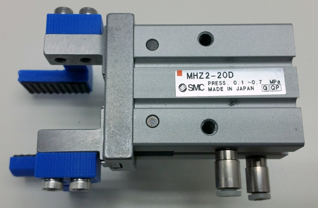
For the pneumatic parts can be used similar parts as shown in the example “Pick and Place using pneumatic gripper”
Disclaimer: While the Zacobria Pte. Ltd. believes that information and guidance provided is correct, parties must rely upon their skill and judgement when making use of them. Zacobria Pte. Ltd. assumes no liability for loss or damage caused by error or omission, whether such an error or omission is the result of negligence or any other cause. Where reference is made to legislation it is not to be considered as legal advice. Any and all such liability is disclaimed.
If you need specific advice (for example, medical, legal, financial or risk management), please seek a professional who is licensed or knowledgeable in that area.
Author:
By Zacobria Lars Skovsgaard
Accredited 2015-2018 Universal Robots support Centre and Forum.